Nomenclature How a sling works Slings and Pouches Release Pins
Tuning Triggers Axles and Counter Weights Basic Numbers Scaling
Simulators Theory Stuff Links Some Math Front page
Plans!
Contact Ripcord
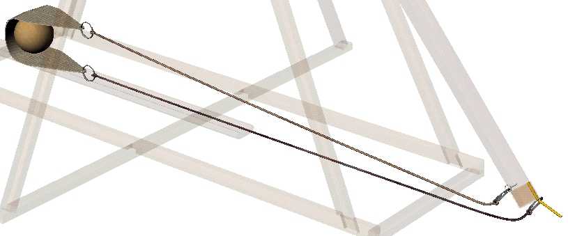
Ripcords Tennis Ball Trebuchet
|
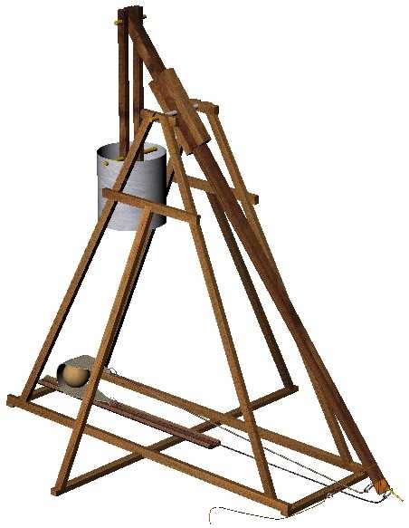
Designed for hurling tennis balls, this 30 inch (axle height) Trebuchet is a working model suitable for learning the fundamentals of Hinged Counter Weight Trebuchet.
The base is 34 inches long and 31 inches wide, making it suitable for many projects that are restricted to 1 meter dimensions.
Complete dimensional and assembly information is included, plus how to make a pouch.
A material list is included with suggestions for optional materials and joining methods.
Although designed with tennis balls in mind, almost any small object can be used. The counter weight can be increased or decreased easily as a part of tuning.
Below you'll find the complete plans and instructions for this machine.
Give the graphics time to load, it may take a while.
Feel free to copy the plans but if you distribute them, please give credit to me.
Oh, and keep things SAFE!
(This model hurled a golf ball through my ceiling when I got a 'little bit' carried away.)
Happy Hurling!
|
If you use these plans or instructions you do so at your own risk. The author of these plans and instructions assumes no responsibility for any injury or damage. This machine has moving parts that may behave in unexpected fashion. Although it is a machine designed to throw small objects, great care should be taken that no person, animal or property should come to harm due to any action by this machine.
This is a set of plans and instructions for building a small-scale hinged counter weight (HCW) Trebuchet suitable for hurling tennis balls with. Although I've tried to make the design fairly simple there are still a few tricky spots in it. These consist mostly of angled cuts in the wood of the frame for the over lapping joints and two holes that have to be drilled at an angle for the axle. I've included the over laps to increase the strength of the joints or to get a better transfer of stresses from one piece to another.
You may decide to exclude the holes for the axle. If you do, you're on your own, but feel free to do so. I would advise that you have a good plan for trapping the axle in some manner rather than letting it just sit on top. It is possible to let it rest in a shallow groove on top, but sometimes conditions arise that will cause it to jump out of the groove and this could lead to damage to the machine and possibly people.
It is possible to build this design without the over lapping joints, but you will have to decide if it is worthwhile for you to do so. There are no nails or screws to hold the frame together, although there are 3 eye-screws as part of the trigger and sling. A wood glue is used and although this means taking a longer time to assemble the machine there is less risk of splitting these relatively narrow pieces of wood and the glue, if applied properly, will make a stronger joint.
The frame is supported off the ground by the three cross members on the bottom. I choose this design over one that has the entire bottom of the frame in contact with the ground because often the surface it rests on is not flat. This causes the machine to ‘teeter-totter' a bit and can put unwanted stresses in the frame as well as making consistent hurls almost impossible. My design helps eliminate this problem by giving the machine a type of tripod stance. It isn't perfect but does put the load bearing points on the ground with a large footprint.
I have built this design. It works. I would discourage you from trying this test but I have balanced my entire weight on the top of the frame, without the throwing arm, all 150 pounds of me. It held. I should point out that the frame was designed to support the loads and forces of a Trebuchet and yet be quick and easy to build. So if you try to use it as a lounge chair it probably won't work. If you grab it by one corner and shake it around hard, it will probably collapse. Don't force it to take on loads it wasn't designed for.
The CW hanger is longer than the ‘standard' model, putting the center of mass of the CW itself at a longer distance than usual from the end of the beam. This is due primarily to the design of the CW itself, which consists of a coffee can. The longer hanger is not a design problem; in fact it improves performance a bit.
My design is NOT intended to have the look and feel of an authentic Trebuchet. It is intended to throw tennis balls and other small payloads. If you want to make it look ‘more real', go for it.
I have included simple designs for a sling, pouch and trigger but feel free to come up with your own designs. You could also visit my site at http://www.geocities.com/rip_rap and look over the pages there to learn of various types of each.
I won't say how far this design will throw anything. Too much depends on how you build yours, what your throwing, sling design, exact masses involved, etc. So if I don't say anything then nobody can complain about “...so why doesn't mine throw as good as yours?”
However, I will say that the arm ratio is 4:1 and the axle height is 30 inches.
If the payload is one tennis ball (.125 pounds new) and the CW ‘box' is filled with the following materials then the CW/payload mass ratios are:
Water (<6.8 lbs.) 54:1 (the water will no doubt keep spilling out)
Dry Sand (11 lbs.) 90:1 (this too can get away unless you modify a lid for the ‘box')
Wet Sand (13.9 lbs.) 110:1 (same here, but not nearly as bad and sand is cheap, so are rocks)
What You'll Need
Materials
There are NO nuts or bolts in this design, just three eye screws. There are places where you may decide to use nuts, bolts or screws, feel free to do so. I would not use nails unless you pre-drill to prevent splitting.
(A) Steel rod, 5 inches long by 1/8-inch diameter, cut into two pieces 3 and 2 inches each.
This is for the release pin and trigger pull pin. If steel is not available try to get something that is pretty stiff yet able to bend without breaking. Bending is how you will adjust the pin angle. Coat hanger wire can work, but if the payload is too heavy the pin may bend.
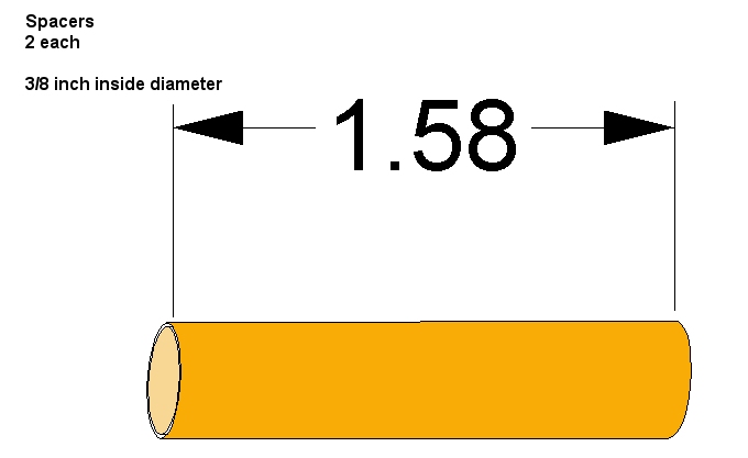
(B) Pipe, 2 pieces each 1.58 inches long, inside diameter should be a slip fit over the 3/8-inch main axle.
This is use for spacers on the throwing arm axle, to keep the arm centered. Outside diameter can be almost anything but ½ inch should be your upper limit. If you can't get this, maybe you have a lot of washers that will fit?
(C) Steel rod, 17 inches long by 3/8-inch diameter.
This will be cut into three pieces (7”, 3.5” and 6.5”) for the three axles used. This steel should be pretty stiff stuff since it has to support the masses under ‘dry fire' conditions. To test, take a 7 inch length, support it between two bricks (or something) and put about 100 pounds of weight in the middle of it. If it doesn't bend, okay. I'm using a piece of ‘mild' steel and it has been holding up fine, even when dry fired.
(D) 3 Eye screws.
These should have an ‘eye' about ¼ of an inch in diameter and a threaded length of around ¾ of an inch. This is what the ‘fixed' end of the sling will attach to as well as being part of the trigger.
(E) Coffee can. 34.5 oz size.
This is going to be the CW ‘box'. Don't drink coffee? Then get one from the neighbors or use a sack full of rocks or whatever comes to mind. Just make sure it will clear the frame when swinging and doesn't hit the ground when the beam is vertical.
(F) Wood Glue
Don't use the balsa wood modeling cement. Use some really good stuff, it's cheap. I used “Titebond II”. About $3.00 for a 8 oz. bottle and most of it is still in the bottle! This stuff is for outdoor use, but cleans up with water.
(G) Twine
Used for attaching the pin release and can be used for the sling as well. I'm talking about the brown stuff that is sort of rough. Not bailing twine but more like what is used for wrapping boxes for mailing. It is cheap and carried in most stores. If you can't break it easily with your hands, it is probably good enough. Feel free to substitute what you want but look over how it is used first so you'll have a better idea of what you'll need.
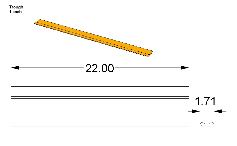
(H1) ¼ round molding 22 inches long. (Optional)
This is for the trough. Not so cheap, so use what you want, even a flat piece of cardboard. If you can though, make something that has a ‘U' or ‘V' cross-section to it. This will help aiming and can even help keep the payload from falling out of the sling. It should have trough a little bigger than the sling and payload together.
(H2) ½ inch Velcro, 2 pieces about 6 inches long each. (Optional)
Used for the trough, so if you don't have a trough you won't need these. But if you do, you can fasten one side of the Velcro to the frame base and the other side to the trough. This not holds the trough in place but is really easy to adjust for aiming!
(H3) Staple gun. (Optional)
Used to hold the Velcro in place. An office size stapler will work, but if you have access to a larger version use short staples in it to keep from splitting the wood.
(I) 4 Key Rings. (Optional) They better be strong! So far I've only blown out one but the others are doing fine. Small welded steel rings are better, say anywhere between ½ and 1 inch in diameter.
(J) Wood, 1 x 1 x 46 inches, Two pieces that are 1 x 1 x 7 inches and many pieces ½ x ¾ inches.
The 1 x 1 is going to become the throwing arm. Although it can be used as is, my design calls for it to have a taper. Look at the plans to see if this is something you can do or have done for you. The ½ x ¾ inch pieces will all have some special cuts made to them but start off with the following lengths:
½ x ¾ inch 'clear' wood in addition to the Throwing Arm as in (J) above.
|
Quantity
|
Length (inches)
|
Location
|
|
4
|
34
|
Legs
|
|
2
|
24.75
|
Outriggers
|
|
2
|
10.5
|
End Cross Beams
|
|
1
|
31
|
Outrigger Beam
|
|
2
|
34
|
Long Beams
|
|
2
|
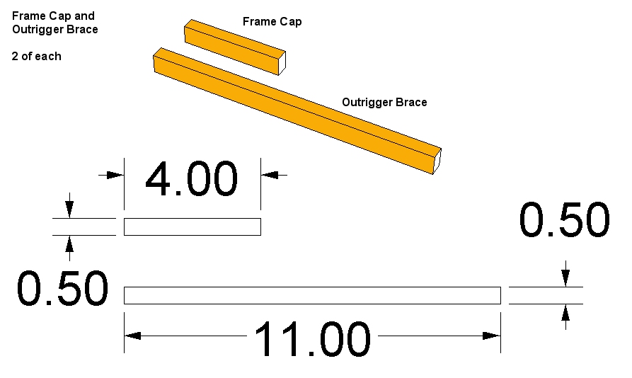
11
|
Outrigger Braces
|
|
2
|
4
|
Frame Caps
|
|
2
|
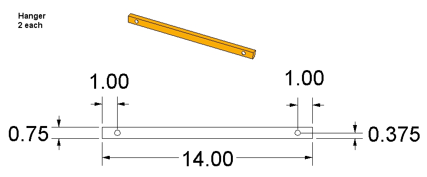
14
|
Hanger Arms
|
Total length of ½ x ¾ (not counting saw cuts for lengths) = 363.5 inches (30 feet 3.5 inches). So get a 1 x 6 inch board 8 feet long (which will measure ¾ of an inch thick) and either cut ½ inch wide pieces out of it yourself or ask the lumberyard to do it. They often do this for free. BUT! Make sure there are NO knots in the wood! These pieces of wood are going to be so small in cross section that even one knot could be disastrous, so inspect it carefully. The same is true for split and cracks of course.
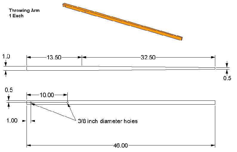
Throwing Arm (1 piece)
1 x 1 x 46
Arm Braces (2 pieces)
1 x 1 x 7
All three of these pieces should be hard wood of some sort, check the plans for the tapered shape, ask the lumber yard what they have in stock and then see if they'll cut the taper for you. Standard soft woods might work (I haven't tried it) but get a hard wood if you can.
Tools
A Drill with a 3/8 inch bit. A 1/16 bit for a pilot hole for the eye screw, or whatever size needed depending on the exact eye screw you use. The bit should have a diameter smaller than the threads of the eye screw, close to the size of the solid portion of the threaded area but as if the threads were missing. If you have access to a drill press, great! This will make drilling the holes at the correct angle very easy.
Scissors to cut Velcro and twine.
Small wood clamps or rubber bands to hold joints together while the glue dries. I've even used the large paper binder clips.
Saws This really depends on how good you are with tools and what you have available. A table saw can do all the needed cuts, if you know how to use it fully. (The first time I made this design all the cuts were made with a fine tooth hack saw blade and a small wood chisel!) But if you have access to a miter box and a router you'll save some grief and time. If your cutting the taper on the throwing arm yourself then you should have a table saw available, most miter boxes won't be able to do it, although it's possible with a good router. Check the plans and see if you can do it yourself or need some outside help.
Heavy duty wire cutters (dikes) For cutting to length the release pin, if needed. A hacksaw with fine teeth can do the job too.
Small hammer and a sharp punch Used for putting two holes in the coffee can. If you've another way of doing it, fine.
Pliers/Visegrips To bend the release pin.
Fine tooth file For de-burring the ends of all the axles and the release pin. A sharpening stone can work too.
Sandpaper, paint, laquer, etc. Your on your own with these. I did put a dark stain on the throwing arm, but paint or not as you choose, just keep it out of the axle joints. Sandpaper if you wish, it can reduce slivers later on, but again that's up to you.
Minimum tools needed: Knife, hacksaw and pliers.
No matter what tools you use be sure they are in good working condition. Use body protection (eyes, ears, etc.) as required. Keep all glues, paints, finishes and other volatile materials in their appropriate containers when not in use. Hey, just keep things safe.
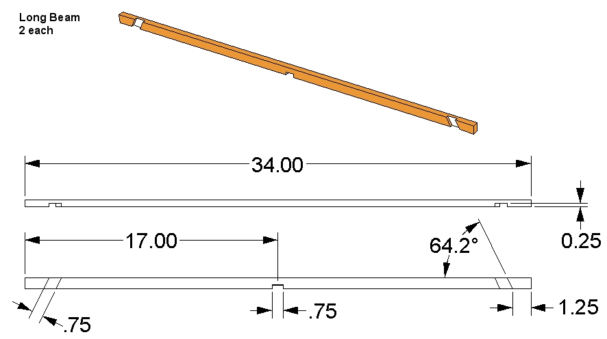
One last note about these plans; You'll notice a lot of odd angles and lengths. This is due to the way I designed the machine. With a base 'this long' and and axle 'this high' I needed legs of thus-and-such a length. The angles are a result of those lengths and relationships. A similar process for other components gave simliar results. If you see an angle to be cut at 64.2 degrees, do not sweat it. If you lay out the pieces and make a line on the object piece, using the mating piece as a guide, you'll end up close to the 64.2 (or whatever angle your going for).
Okay, let's get started.
Throwing Arm or Main Beam
This piece has a taper to it through the vertical plane. The taper starts 13.5 inches from the CW end and ends at the tip 0.25 inches from center line, leaving a 0.5 inch width at the tip. Note that the taper does NOT start at the axle hole, but beyond it. This is so we have a flat mounting surface for the axle reinforcement blocks that get attached later. Note that you need to cut BOTH sides to get the taper in the center of the beam. 2 holes get drilled at the locations indicated below. Use a 3/8-inch drill bit. These holes need to be as nearly perpendicular to the beam as you can get them, since they carry axles, especially the one for the main axle at the 10 inch location.
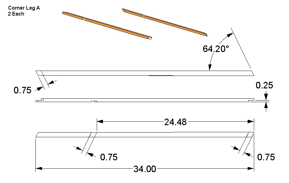
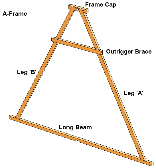
Corner Leg A
In this view there is only one leg but a ‘front' and ‘back' view of sorts to see the cuts on both sides. The half lap cuts made are ¼ inch deep. If you can't measure the 64.2 degrees easily, there is a simple way to mark it. Lay two of the legs on a flat surface with the ends spaced apart like they will be when assembled. Now lay a straight edge across both pieces, ¾ of an inch from the edges and mark a line. Do the same thing again for the 24.48 inch location. Then create a parallel line to each of those marks ¾ of an inch away.
Got all that? I know it may be a little confusing so look at the completed machine and you should be able to figure out where the cuts go and how their locations were determined. Just keep in mind the half laps on the ends are on opposite sides of the leg.
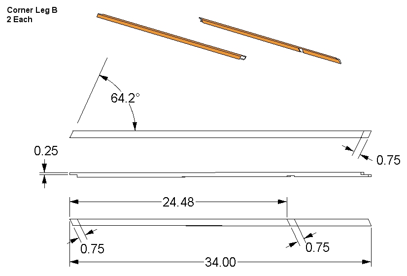
Corner Leg B
This is the second pair of legs, which are a mirror copy of the first ‘A' set. Not so obvious to some is the fact the either side of the machine can be turned around and become the other side. Anyway, create this leg twice, as with the A legs.
Long Beam
There are two of these also, but no mirror image pieces needed.
 Trough
This is a simple piece of quarter-round molding cut to length. The length isn't really critical, nor is the exact shape or size. It should be long enough to provide support to the pouch until it rises upwards during the first section of the throw. The whole idea is to simply support the pouch/stone combination until take-off. It can also act as a way of aiming.
Optional: Take some of the Velcro and staple it to the bottom of each end, a couple of inches will do. Run them length wise. The other half of the Velcro gets stapled to one of the Cross Beams (the one on the back end of the machine) and the Outrigger Beam. This arrangement allows you to move the Trough where you want but will hold it in position during a hurl.

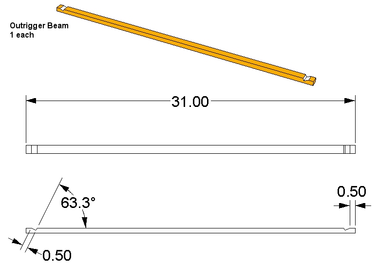
Outrigger Beam
Only one needed. Notice that the only cuts, other than for length, are the two sloping notches at the ends. These are where the outriggers will sit.
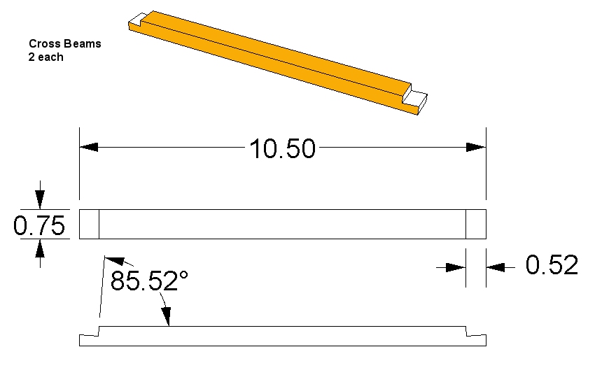
Cross Beams
Two of these, but pretty simple again. Note the angled notches on the ends, they could be kept at simple 90 degree cuts instead, if you use plenty of glue. This is where the Long Beams will be fastened and they have that tilt inward towards the axle, but it isn't much so… Use your judgement.
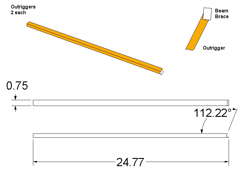
Outriggers
Two of these, both the same. The length of these really should be fitted to the frame after it's assembled, so you may want to cut the notch now but leave the finished length until later. The angled notch on the one end gets fastened to the Beam Brace, one on both sides of the machine. This is why it has such an odd angle. The other end of the Outrigger is square cut and fits in that angled cut on the end of the Outrigger Beam.
 Hangers
Two please. Hey, no more cutting odd angles, Yay! Two holes drilled as indicated, 3/8-inch. These are what hold the CW to the short end of the throwing arm.
Frame Cap and Outrigger Brace
No holes, no angles, what could be simpler? So I gave them both to you at once. 2 of each please.
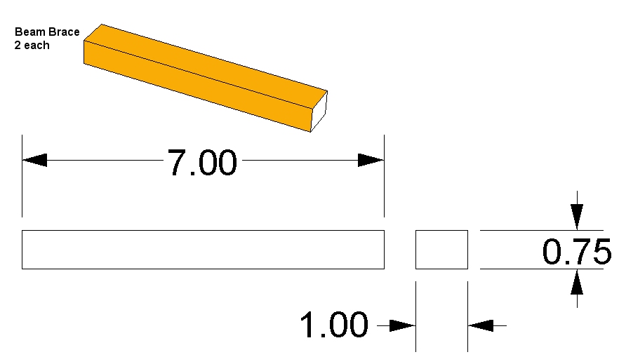
Beam Brace
Note: These are NOT ½ x ¾ stock. They will be used to reinforce the throwing arm around the axle. Two needed, 1 x ¾ inch and 7 inches long. You could almost chew these to size.
Spacers
Two. These are used to keep the throwing arm centered. You may wish to wait before cutting these to length since there is bound to be some difference between your machine and mine. The outside diameter can be anything really, but make it large enough so that the ends don't fall through the hole in the throwing arm or the frame caps. You might even put some washers against each end, which could save a little wear and tear on things. Or not.
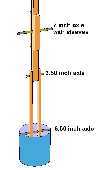
Axles
I'm not even going to include a picture for these, just cut the 3/8 inch round stock (steel) in 3 pieces that are 7”, 3.5” and 6.5” long each. If you have the resources to do so, you could put threads on the ends of each of these and then put nuts on to hold things in place. (Hint: You could visit the hardware store and buy 3 bolts of the appropriate size.) I haven't though and everything stays put pretty well. I do check it often though.
Counter Weight
Put two holes, 3/8 inch diameter, on opposite sides of the coffee can, right up near the top (open) end of the can. The 6.5 inch long axle will go in here. Mine has bent the edge of the can over time but it still works fine. You could put the axle a little lower and nut and washer things to beef up the sides of the can a bit. Up to you.
Eye Screw
The eye screw goes on the bottom side of the throwing arm. Pre-drill the hole for it to help prevent splitting that nice throwing arm you just made. Use the small drill bit. It should be located as close to the end of the beam as is reasonable, depending on how much room you have after putting the release pin on. So do that first then put in the eye screw.
Release Pin
If you've already cut it to length that's good enough for now. More later during assembly.
Assembly
( and about time too! )
If you haven't beaten me to it and started hurling things already, I'll go over the steps needed to put this thing together. This will take time because you want the glue to dry for each sub-assembly before moving on to the next step.
You can, if you wish, use different methods of fastening things together, like nuts and bolts, screws, wooden pins, rubber bands, wishful thinking, bubble gum, spit, etc. You can even change up the design a bit to accommodate your fastenings. You can change the design anytime you wish! It is totally up to you. The hardest part is waiting for that last glue joint to dry before you get to hurl anything. Do yourself a favor and give it time to dry! Overnight for the glue I used was sufficient.
Have plenty of room to work in, this thing gets a little hazardous if your swinging pieces around in cramped quarters. Have some ventilation going to keep the glue fumes from giving you a headache, or worse. Put newspaper down on your work surface. The glue WILL slop around a bit but if it sticks to the newspaper it peels off easily, not so easily from momma's dining room table though. I used a big pile of rubber bands to hold joints together while glue dried. Afterwards I simply cut the rubber bands and peeled them off. If you've some nice clamps you want to use instead, go for it.
Start with 1 piece each of ‘A' Leg, ‘B' Leg, Long Beam, Outrigger Brace and Frame Cap. Notice which side each piece lays on and how it orients with the other pieces. The Frame Cap will NOT be flush with the legs. The Outrigger Brace should measure about 22 inches from its bottom side to the bottom of the Long Beam. Follow the directions for the glue your using and glue all these joints together. Use rubber bands, some weights, clamps or whatever to hold them together while the glue dries.
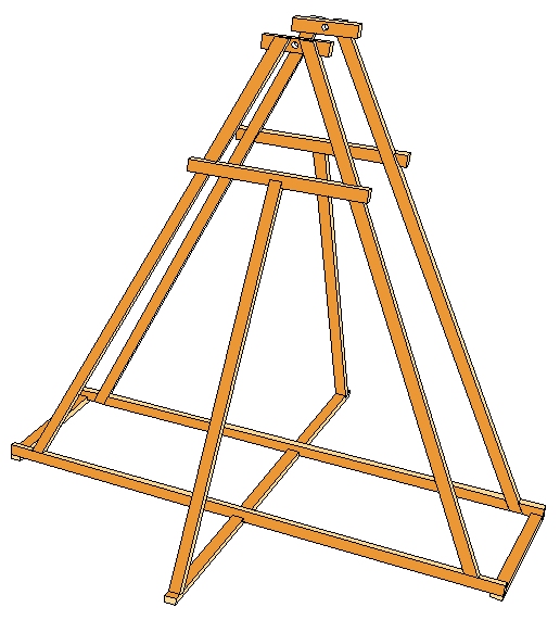
Once you have one completed, set it to the side and build another one just like it. Both of the A-Frames should look the same and (hopefully) measure the same from the ground up to each cross piece.
Assembly of both A-Frames, Cross Beams, Outrigger Beam and Outriggers.
Start by dry fitting (no glue) both Cross Beams in position, hold with rubber bands or clamps. Place the Outrigger Beam in position which should be centered between both A-Frames. Dry fit the Outriggers in place. All this may take a little practice so take your time. Slide the Outrigger Beam back and forth until both A-Frames are at the same angle inward. Make a pencil mark to show that location on the Outrigger Beam. Double check the two holes in the Frame Caps by measuring from the ground (table top?) to the holes, they should both be at the same height, if not try moving the Outrigger Beam back and forth until they are. If needed you might try adjusting the length of one of the Outriggers to help get things place correctly. You can do this with a thin piece of wood or cardboard.
Once you are sure of the positions of all pieces, start gluing them together. Start with the Cross Beams then the Outrigger Beam and lastly both Outriggers. Before the glue sets double check all positions. Once your satisfied, leave it alone where it won't be disturbed until the glue is dry. Now is a good time to work on the Throwing Arm and Counter Weight.
Throwing Arm and CW assembly.
Place the two 7 inch Beam Brace pieces 6 ½ inches from the end of the Throwing Arm and glue, one on top and one on bottom. You may wish to wrap some twine around these as well for more strength. These are intended help prevent the Throwing Arm from breaking at the axle pivot. Depending on the quality and type of wood your using it may not be needed, you'll have to judge that for yourself.
The Release Pin is placed on top in my design, but one school of thought puts it on the bottom. There are advantages either way.
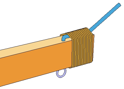
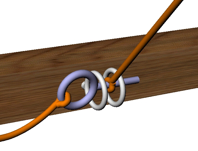
Tip Detail
The Release Pin is held on with the twine, as shown below. Make the turns neat and tight. I used glue in this area also, to help prevent the twine from fraying and give it all a little more strength. You may wish to put a right angle bend in the Release Pin, under the twine, to help keep it from twisting and insert it into a pre-drilled hole in the top of the Throwing Arm. The Eye Screw is placed on the bottom and as close to the tip as you can get without interfering with the twine wrap.
Hanger Assembly
Again, you may if you wish, use bolts and nuts for some or all of the axles. To assemble the Throwing Arm unto the completed frame, push the 7-inch axle through one of the Frame Cap holes, put on one spacer (1.58 inch tube), then the Throwing Arm followed by the other spacer.
Pouch
You can make a pouch suitable for tennis balls and other similarly sized objects out of almost anything. The keys to a good pouch are reliability, ease of construction and size. Reliable in the sense that you can use it more than once without it falling apart! Construction, no need to get super fancy with these things when a simple design works very well, sometimes better. Size, this is probably one of the toughest ones. Too big and it may not let go of the payload in time, too small and it may let go too soon.
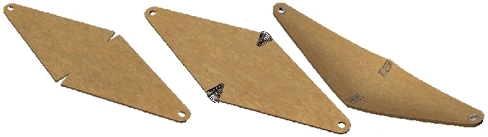
A pouch should have a little bit of a ‘belly' to it. This will help cup the payload during the first portion of hurling yet not trap it when time to release. You can make one based on the images below. For a tennis ball, make the diamond shape anywhere from 8 to 10 inches long and 5 or 6 inches wide.
Cut a ‘V' notch at each side corner and then sew the resulting edges together, this will make the material form a ‘belly' or cup. Not too much, we do want it to let go of the ball. Now put a couple of holes in the long ends. You can reinforce these with metal grommets, which may keep the holes from tearing out too soon, if the grommets are set correctly.
Make the pouch out of almost anything lying around, a scrap of blue jeans, thin leather, naugahide or whatever. If you plan on throwing sharp rocks you may want to choose a material that will withstand those sharp corners.
Trigger
Use the other two Eye Screws and screw them into the middle of the rear Cross Beam. Bend the 2 inch piece of 1/8 inch steel into a trigger pin by simply putting a loop in one end. Tie a good length of Twine to it, long enough to stand away from the machine for firing. Use more Twine for the trigger line itself, which is tied around the Throwing Arm about 2 ½ inches from the tip of the Throwing Arm then tie a loop in the other end. The loop should be big enough to fit loosely around the Trigger Pin. The Trigger Line should be short enough to hold the Throwing Arm tip down almost to the ground.
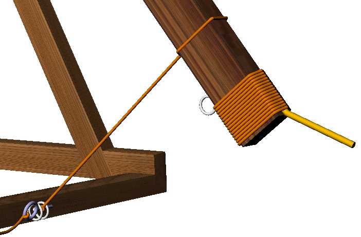
Sling
Cut two pieces of twine and tie each of the four ends to 4 key rings. One key ring is attached to the eye screw near the Throwing Arm tip, another to one of the grommets on the pouch. The second sling line is attached to the remaining grommet and the last key ring becomes the Slip Ring that slides over the Release Pin. Cut the Sling Lines extra long so you can adjust the length later without having to cut new lines. For a starting length though, measure the distance from the Release Pin to the Throwing Arm Axle. The Tennis Ball should sit this same distance away from the Release Pin.
Throw some sand or rocks, whatever you like, into the coffee can. Recall what I mentioned at the beginning of these plans,
Water (<6.8 lbs.) 54:1 (the water will no doubt keep spilling out)
Dry Sand (11 lbs.) 90:1 (this too can get away unless you modify a lid for the can)
Wet Sand (13.9 lbs.) 110:1 (same here, but not nearly as bad and sand is cheap, so are rocks).
I would suggest you start with the can filled only half way, just to test things out, then continue putting more into it until you've reached its capacity. Please don't fill it with steel or lead! This machine was NOT designed for that much mass! The next step is to….uh…gee. There is no next step because YOUR DONE!
If you can't figure out how to cock and fire the little beast you've just built, then you haven't been doing your research.
Please! Keep safety in mind at all times. Keep people away from it while firing, the sling alone can do some nasty whipping around long after the payload is gone. Keep in mind that these things have been known to shoot not only towards the target, but straight up and backwards, so keep people out of the line of fire in BOTH directions! Inspect your Trebuchet often, like before and after every shot. Everybody will be safer and you may save your machine in the process.
Questions? Drop me an e-mail at Siege@localnet.com You can also visit my web site for newbie flingers at http://www.geocities.com/rip_rap
Happy Hurling!